PID Control on an Opto22 groov RIO
This tutorial details the actual control logic for implementing a PID control loop on an Opto22 groov RIO. The RIO has four built-in PID loops, and we will use one loop to control an analog output connected to a steam valve based on the temperature of the thermocouple input on Channel 0 that we set up in part 1 of this series.
Today, we will set up the analog output, enable the PID loop, set up links to the I/O channels we are using, add variables to change the setpoint and tuning values from Ignition, and give you a fully functional PID control loop on the RIO.
Configure the groov RIO’s Analog Output
First, we will add an analog output channel to the RIO with channel 4 where we will set up a 0-20 mA signal. Go to the groov Manage homepage, click “I/O Channels”, then click “Channel 4”, then “Configure”, and select “0-20 mA output” then “Save”. You can also enable MQTT by enabling “Public access” like we did in a previous post.

Adding the PID Loop
The next step is to enable the PID loop itself. On the groov Management page, click on “PID Loops”, click PID Loop 0, then click “Configure”. Enable the PID loop, and you can also enable the Public Access options down below to get values into Ignition via MQTT. Then click “Save”. Next, we will dive deeper into the configuration steps to enable writing the setpoint from Ignition.
A PID loop complication we will dig deeper into is setting up the setpoint so that it can be changed by Ignition. Based on the architecture of the groov RIO to write values to the PID loop variables, we will need to utilize the MMP address space and map those values to the PID values. For this tutorial, we will be configuring the setpoint as a value we can write from Ignition.
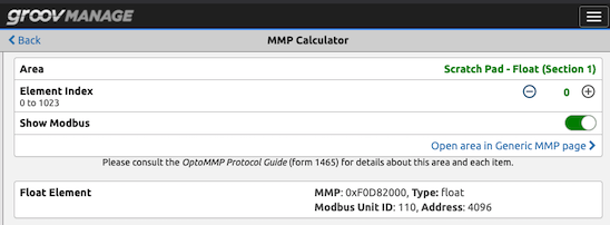
The first step is to configure an MMP address to use for the setpoint. To do this, go back to the groov Management homepage and click “I/O Tools” then “MMP Calculator”. Once on this screen, you will click the first item on the page to select the MMP Area, and choose “MMP Scratchpad - Float (Section 1)”.

Now, you can see the scratchpad addresses. For this post we will just use item 0 in the float scratchpad section. To grab the address for this MMP value, copy the value listed here, in the screenshot below it is 0xF0D82000.
Once you have copied the address, go back to the PID Loop configuration for the PID loop you configured, and set it up for the setpoint value. Click on the “Value Type” in the setpoint section of the PID loop configuration page, and select “MMP Address”. Then, in the MMP Address field paste the address you copied on the MMP Calculator page.
Modbus to the Rescue!
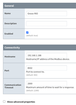
To access the MMP addresses in Ignition, the groov RIO gives us a handy route using Modbus TCP. First, create a Modbus Device in Ignition, using port 8502 as the default for the RIO instead of the standard 502. You will also want to check in Advanced Properties and make sure Zero-Based Addressing is enabled for this connection.

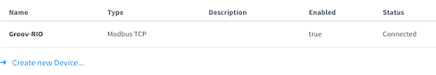
Once you have the Modbus Device created, you can create a tag in Ignition and point it to the relevant Modbus address. Now you will be able to change the value in the RIO. If you look at the MMP Address screenshot above, you will see below the MMP address there is a Modbus address. In this case it is Unit ID 110, Address 4096. In Ignition, we will use this to build our OPC Tag Path using the device name giving us [Groov-RIO]110.HRF4096
The HRF defines a floating point register, and the other items follow the format of Modbus TCP addressing for Ignition, which can be seen in the Ignition’s documentation.
Once you have the tag configured, you can look at the PID loop in the groov Management page and watch the setpoint value update as you change it in Ignition.

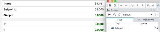
From here, you can adjust the setpoint from Ignition, then go into the groov Management page to the PID Loop visualization page to tune the control loop itself by adjusting the values for the P, I, & D gains.

Now, you have the ability to do PID control using your groov RIO. With this, you can control an actual process using PID control using just a RIO, along with a bunch of spare I/O points you can use for other devices.
In the next tutorial, we’ll take a break from controls for a bit and dive into how to use the RIO for remote access before moving into how to replace an off-the-shelf PID controller with a split time range proportional controller using Node-RED on the RIO. Find all of our Opto22 Tutorials.
Ready to start a Project with Opto22 Hardware and Ignition
Corso Systems is an official Opto22 Partner!
Schedule a short no-obligation intro call with Cody Johnson in Sales today
Or contact us with your project details