How to Implement a Unified Namespace with Ignition
We’ve done plenty of talking about the concept of a Unified Namespace architecture. We’ve posed the question asking if Ignition is a Unified Namespace, and we’ve talked at length about how MQTT and Sparkplug B play a pivotal role in implementing a Unified Namespace.
While many other online resources discuss Unified Namespaces, they tend to focus on topics such as how Unified Namespaces and the ISA-95 Standard might work together to structure data in a hierarchical way. What we are going to do in this post is show you HOW to implement a Unified Namespace. To keep it simple we will focus on process data, a common component in an enterprise level namespace. In this example, we’ll use the same digital manufacturing technology we use at Corso Systems every day to help manufacturing companies streamline their operations and increase revenue and profits.
Download our ebook - Unified Namespaces: The Ultimate Guide
And yes, you can replace any of the components in our example’s architecture with anything else: Allen Bradley PLCs, Siemens PLCs, B&R, Schneider Electric, or any other brands. You could also include more complex systems like generating a list of product codes from an ERP system to send data to an MES system for example. The HiveMQ broker in our example could be another cloud-based broker, a Chariot Broker from Cirrus Link, or even a Mosquitto broker. Essentially, the components in our example are ones we’ve chosen from the options we like and have used in the past.
Our Unified Namespace Architecture
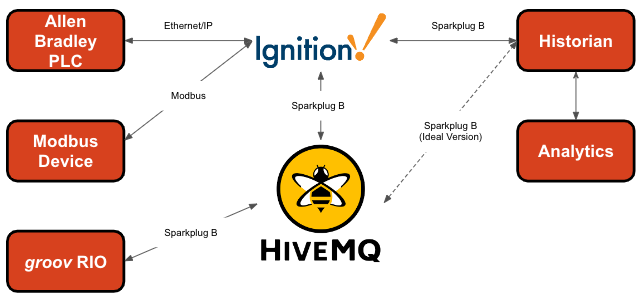
Following the lead of the popular cloud-based MQTT Broker HiveMQ, we will be implementing an architecture like one in the diagram below, but with fewer nodes.

A diagram of an MQTT broker used to house UNS (unified namespace)
We’ll start with an Opto 22 groov RIO device to act as a Gateway Edge of Network node, and tie in a temperature sensor. Next, we will connect an Allen Bradley PLC to Ignition to act as a PLC device, as well as a separate Modbus device. We will connect Ignition to the MQTT Broker to act as our SCADA host. Finally, we will connect to Clarify to represent our Historian and Analytics nodes. We’re choosing HiveMQ to be our MQTT Broker since we like their offering and it works well with all of the above technology.
If we look at this as a brownfield scenario—where we would typically add a Unified Namespace on top of an existing system—we will need to make some compromises to reduce the time to value on this project.
Allen Bradley doesn’t currently support MQTT directly, though you can convert the data with MQTT gateway hardware or software (much like having to use Prosoft Modules to support Modbus data with Allen Bradley hardware.) So, we will connect our Allen Bradley PLC to Ignition for communication, then use the Cirrus Link MQTT Transmission Module to send data to the HiveMQ Cloud MQTT Broker so other systems can access the data through the Unified Namespace.
Since we are using the Cirrus Link Transmission Module on the Ignition gateway for the PLC data, we will also use it to connect to the Clarify MQTT Broker. This will simplify the architecture for our example. If you wanted a “complete” Unified Namespace through this example setup, you could just as easily use the Enterprise Bridge functionality of HiveMQ to connect the HiveMQ broker directly to the Clarify Broker. However, that adds an additional layer of complexity to the system for our example here and would require a much longer post to explain properly. Often, “perfect is the enemy of good.” So for the sake of brevity, we will implement a functional example to get started, and worry about making an ideal version later.
Need help with your Ignition project? Schedule a meeting with Cody Johnson in sales, today!
The Brains of the Operation
Configuring HiveMQ

We’ll set up HiveMQ first, since it is the central piece of technology everything else will connect with. (Please note that we also have a detailed post about how to set up a HiveMQ account as well as getting a groov RIO set up to send data to HiveMQ.)
First, sign up for a HiveMQ account. For the sake of this example, choose the free plan. But if you upgrade to the paid plan, you can access more functionality like the Enterprise Bridge. Since we are just getting started, we can use the free trial for up to 100 devices. Setting up your free account will also create a cluster for you to use for your HiveMQ broker.
Once your HiveMQ account and cluster are set up, copy the cluster’s URL for use in the groov RIO and Ignition when we connect those to the broker:

Example of a free HiveMQ Cloud Cluster
You will also need to click the “Access Management” tab to create a user so you can login to the broker from your MQTT clients. In the example below, we created “corsohive” and “corsorio”:

HiveMQ Cluster Details

Example Opto 22 groov RIO configuration page. Please note you will prefix the URL with ssl:// instead of tcp://
Now, we have everything we need set up on HiveMQ for our project!
Connect the groov RIO to HiveMQ Using Sparkplug B
Next we will open up our Opto 22 groov RIO configuration page, click “MQTT”, “MQTT Configuration”, then “Add MQTT Broker”.
Enter your HiveMQ information, and since the free trial version of HiveMQ doesn’t handle mutual certificates, you don’t need to worry about them for now. But, you will add your URL, username, password, and port.
Connect Allen Bradley and Modbus PLCs to Ignition
Connecting devices to Ignition is very straightforward. If you haven’t connected a Modbus device to Ignition before, here is the documentation. Likewise, here’s the documentation for connecting Allen Bradley PLCs. here is the documentation for that.
Connect Ignition to HiveMQ Using Sparkplug B
Next, we will connect Ignition to HiveMQ using the Cirrus Link MQTT Engine Module to receive data and the MQTT Transmission Module to send data.

Configuring the MQTT Engine Module
Install the Cirrus Link MQTT Engine Module on your Ignition gateway. Then go to your gateway webpage, and click the Configure tab. Scroll down to “MQTT Engine” and click “Settings”.
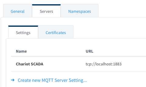
This will bring you to the MQTT servers configuration page (seen in this screenshot).
You will likely see the default Chariot SCADA server already configured. Since we will need to configure for our HiveMQ Cloud Broker, click the “Create new MQTT Server Setting…” link below the list of servers. Here we will name the connection HiveMQ, enter in our URL, as well as the username and password we created on the HiveMQ site earlier.
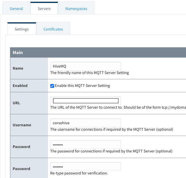
Once you have entered these values click “Save” and you should see your HiveMQ server added to the list and connected.

What you will see when a new MQTT Server is correctly configured and connected.
Connect Ignition to HiveMQ with the Cirrus Link MQTT Transmission Module

The MQTT Engine Module allows Ignition to send and receive data from an MQTT Broker and automatically creates MQTT Tags in the MQTT Tag Provider. To send data from non-MQTT Tags (in this case Modbus and Allen Bradley tags to an MQTT Broker) we will use the Cirrus Link MQTT Transmission Module.
First, download the MQTT Transmission module from the Inductive Automation website and install it on your gateway. Then, on your gateway webpage after clicking the configure tab, scroll down to “MQTT Transmission” and click “Settings”.

Successfully configured MQTT Server Sets
Click “Sets” and create a new server set for HiveMQ by simply clicking “Create new MQTT Server Set” and entering “HiveMQ” for the name before clicking “Save”.
A server set helps you manage redundancy when you have multiple servers using the same server set. In our case, we will want each server to be in its own set since we aren’t using redundancy at the MQTT Broker level in this example.
Next, click the Servers tab and “Create new MQTT Server”. Similar to the MQTT Engine configuration, enter your server name, URL, username, and password. You will also select the HiveMQ server set we created in the last step.

This will add the server to the list. It won’t show as connected yet, since he haven’t mapped any data, but that will happen in a later step.
Connect Ignition to Clarify Using Sparkplug B and the Cirrus Link MQTT Transmission Module
We will follow the same process for connecting the Cirrus Link MQTT Transmission Module to Clarify as we did in the previous step when we connected to HiveMQ.
Before you set up the Ignition connection, you will need a Clarify account, and to set up an Integration and access credentials. A full walkthrough of this process is available on the Clarify support site. Once you have configured your Clarify instance, you can configure Ignition to connect to it.
Now, we will create a Set called Clarify, and assign the Clarify server to it.

Now, we’ve connected all the pieces to the Unified Namespace—which is HiveMQ for this example. Next, we will create tags from the various devices, and build our Unified Namespace.
Unify the Unified Namespace
Now that everything in our architecture is connected, we can start getting data from wherever it originates into our Unified Namespace.
For this example, we will keep the tag list simple so we can teach the concepts. Scaling this up is just a matter of applying some thought to your naming convention and applying it to your entire system. Keep in mind the naming convention you decide on will create your hierarchy for you.
| Device Type | Device Name | Tag Name | Protocol | Address | |
|---|---|---|---|---|---|
| AB PLC | PLC-101 | Tank 1 Level | Ethernet/IP | Tank_1_Level | |
| Modbus PLC | PLC-102 | Pump 1 Speed | Modbus | 40656 | |
| groov RIO | PLC-103 | Ambient Temperature | Sparkplug B | OptoMMP/Modules/Channels/Alex Office/Value |
We want the Unified Namespace for these tags to follow the structure:
Controls
PLCs
PLC-101
Payload will contain Tank 1 Level as a value
PLC-102
Payload will contain Pump 1 Speed as a value
PLC-103
Payload will contain Ambient Temperature as a value
***NOTE*** Before you ask, YES WE KNOW ABOUT ISA-95. If you want to understand our methodology for naming conventions FOR THE UNIFIED NAMESPACE ITSELF, please check out our post on Using ISA-95, Sparkplug B, and Unified Namespaces Together.
When people are looking for process data in the system at the Unified Namespace level, or are trying to integrate with process data using the Unified Namespace, they will likely look at the business in the structure they are most familiar with.
For folks on the business side this might be ISA-95, and for maintenance folks it will PLC code, electrical drawings, network diagrams, or an Excel sheet listing out devices with their data points. Maintenance folks will most likely not be looking at an Enterprise->Site->Area->Line->Equipment layout. For this reason—and having gone through this process on many projects implementing Unified Namespaces over the years—we prefer to break down the data INSIDE the Unified Namespace in a way that most people using the data will find most useful. This may mean you need to expose data in different ways to different people.
Yes this means some folks will need to do a little more work to map the data to some of the domain specific namespaces in a larger architecture depending on their view of the system, however it will save everyone from doing a lot more work to get the system off the ground in the first place.
You may feel differently and that is totally okay. You can absolutely use things like the Parris or Schultz methods and add a long identifier with backslashes or colons to get your ISA-95 equipment model in your Unified Namespace. We will happily support projects with that approach as well, we simply feel it saves a lot of headaches in the long run to map data based on how people will use the data rather than looking at one standard in isolation.
To accomplish this mapping we will first set up the Opto 22 groov RIO. It requires the fewest steps since we are working with Sparkplug B directly on this device.
groov RIO Sparkplug B Mapping
Please check out this post for a very detailed walkthrough on how to get data from an Opto 22 groov RIO to an MQTT Broker using Sparkplug B.
Ignition Sparkplug B Mapping
If you already have tags set up in your Ignition gateway, you can skip the next couple of steps since we are starting from scratch for this example demo.
Modbus
In the Ignition Designer, we will first set up a tag mapped to address HR40656F in the Modbus_PLC device called Pump 1 Speed. This will give us a floating point value for the pump speed. This is pretty straightforward. Wherever you want to configure the tag, create a new OPC tag, and enter the following OPC Path:


For our purposes, we will put this in our Unified Namespace tag provider, so we can see that everything looks reasonable from one view in the Designer.
Now that we have this tag set up, we will move to the Allen Bradley PLC and add the tag we need from it into the Unified Namespace tag provider.
Ethernet/IP

Next we will set up an OPC tag mapped to the Tank_1_Level tag in our AB_PLC device:
Now we have set up both tags that we will be connecting directly to Ignition. Next we will set them up to send data to Clarify. If we were doing this in a production environment, we would use the HiveMQ Enterprise Bridge and map all of the data to go to the HiveMQ Broker only and pass it to Clarify from there. However, we are keeping things a bit more simple in this demo from a licensing perspective.
Sending Data to Clarify from Ignition
To send data from Ignition to Clarify we need to go to our Ignition Gateway, go to Config->MQTT Transmission->Settings, then click the “Transmitters” tab.

Next, click the “Create New Settings…” link below the list of transmitters. Enter the info you want to use for the transmitter name, enter the tag provider you wish to use, and the tag path to the root folder you want to map to. Finally, select the set you want to use. This will select the correct server to send the data to once the transmitter is active.

Depending on your folder structure, you can also set values for the Group ID, Edge Node ID, and Device ID. In our case we will set the Group ID and allow the folder structure to dictate the Edge Node ID and Device ID for us when the data is sent to our broker.

Click “Save” and you will see your transmitter added to the list.

Go back to your servers tab, and now you should see 1 of 1, or X of X connected depending on how many transmitters you are using to send data on this server. In this case, we have two transmitters set up, one for this demo and another for other data outside the demo that we are sending to Clarify.

Now that we have our transmitter sending data, we can go to Clarify and see our new metrics show up. They will display as unpublished since this is the first time we have sent them to the system:

If you click on a value, you will see the configuration dialog for where you can publish it, as well as set values for engineering units, gap detection, sample intervals, and more.


Once you are happy with the configuration click “Publish” and your data will be available in Clarify.


Again, if this was in production, we would set up the connection to the Clarify MQTT Broker directly from HiveMQ using the Enterprise Bridge, however this example shows how you can connect data with the same structure across multiple brokers using the Unified Namespace.
Sending Data to HiveMQ from Ignition
To send data from Ignition to HiveMQ, we simply follow the procedure from above except that we’ll point to our HiveMQ set when defining the transmitter. Since we are sending the same data, this is a very straightforward process.


Now that we are connected, we can look at the HiveMQ web client and see our data coming across. The weird characters we see are artifacts because the web client does not use a Sparkplug B decoder. However, we can still see that data is coming across.

To see actual values come across, you can use a client with a Sparkplug B decoding capability, or in our case we can just look at the MQTT Engine tag provider and see our data there:

Eureka!
With this simple example, we now have data coming from multiple devices with completely different domain namespaces into a completely Unified Namespace. Our setup looks very similar to the HiveMQ architecture diagram toward the beginning of this post, and we are now ready to integrate any additional systems with our Unified Namespace.
Astute readers will note that we are technically duplicating the groov RIO data by sending it to HiveMQ from the groov RIO directly, and from Ignition. And no, this would not be how we would want things to operate in a real-world scenario. However we are not going to demonstrate every possible edge case in this post. This idea is left here as a thought exercise for the reader to think through how to structure mapping data to a Unified Namespace and Domain Specific namespaces.
To solve this problem, we could use a custom property on the tag to exclude it from the payload as described in the Cirrus Link documentation. We could use the data from the groov RIO in Ignition without creating a reference tag for it it in our Unified Namespace tag provider, or we could set up a second set of reference tags to send to HiveMQ directly for the non-duplicate data. If we were using HiveMQ’s Enterprise Bridge tool it would entirely eliminate the need for the redundant data mapping.
This goes to show, even building a simple Unified Namespace can have complexity and requires thought and planning to successfully execute. Even if you put in a lot of time and thought to your Unified Namespace, over time you may still need to refactor when you run into issues like this and that is totally okay! What got you to here won’t necessarily get you to where you are going!
Wrapping Up
We hope this was a helpful guide for the absolute basics of building out and integrating a Unified Namespace! It tied a lot of different technologies together, demonstrated some of the hurdles you will inevitably run into when building out any Unified Namespace, and gave you some ideas about how to solve those hurdles as they appear.
If you need help with your Unified Namespace project or have any questions about the process please reach out and let us know!