Recipe Management in Opto22 groov View - Part 1
Using groov View on some recent projects required us to integrate with our standard furnace recipe system. Our approach uses a database to store the recipes, the HMI to manage (create, edit, delete) them, and the HMI to load them to the PLC.
Normally we would accomplish this using built-in functionality to connect to databases in Ignition. Or, with something like Node-RED to interact with the database and system.net.http calls to interact with the database from an Ignition Edge Installation.
Since Node-RED is already built into every groov EPIC PLC, we can port over our code from a previous Ignition Edge installation, set up a data store in the PLC to interact with Node-RED, and then program the PLC to manage the data. While this is not a particularly complicated process, it does have a few steps. To keep this tutorial easier to digest, we’re releasing a series of three posts: Node-RED setup (part 1 - this post), groov View and Node-RED integration (part 2), recipe management in groov View (part 3), then the PLC code to use the recipe for process control (part 4).
Bridging IT and OT with Node-RED
If you already know how to build web services using things like Ruby on Rails, NodeJS, .NET, etc. you can certainly use them instead of Node-RED on any project. But, when working with Opto22 hardware, those options are more cumbersome to integrate since Node-RED is a first class solution on the groov hardware. So, we are going to use Node-RED.
Just like Ignition, you can install Node-RED on nearly any operating system—and it has an immense amount of functionality out of the box. It can work with Modbus, Ethernet-IP, MQTT, OPC-UA, and OPC-DA. Node-RED can not only interact with APIs, you can build APIs using Node-RED! Heck, you could even build out an entire HMI in Node-RED if you were so inclined.
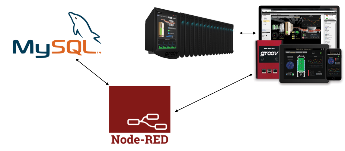
For recipe management, we will use Node-RED as the bridge between our IT layer (the database) and our OT layer (the groov EPIC PLC itself). We will use a simplified version of our well-vetted—by real-world projects—recipe database for this series. We know what the PLC code needs to do, so we will convert and optimize it for the groov EPIC. We also know what the HMI needs to do, and we will build out that functionality. Some of the Node-RED specifics will need to change from out previous projects, so we will build that up from scratch in this tutorial.
Assuming we already have our database set up, we will go through the Node-RED configuration first. Our example database is very simple: one table with a few columns. If you haven’t yet enabled Node-RED, read our guide for setting it up, then return to this tutorial to continue.
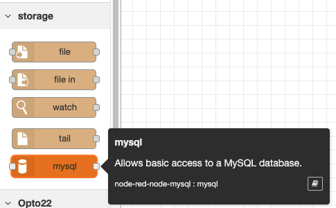
Once you have Node-RED set up and running, navigate to it, then choose the “Manage Palette” option in the menu. Then go to the install tab, to install the node-red-node-mysql library to enable connecting to a MySQL database. If you are using a different database engine, choose the relevant node for your database and install it instead.
Next, drag a MySQL node onto your flow. Select it and go into the configuration to set up your database connection.

On the configuration pane, enter your database settings. In our case, we have a schema named Opto22 and are using the root user to keep things simple for now. Make sure the computer running the database is accessible on the network from your groov EPIC controller.
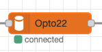
Once you have set up the connection, deploy the flow and you should see that the MySQL node is connected.
Database Interactions 101
The next step is to setup a SELECT statement to get all of the records currently in the database. This will validate that our connection is working, and it’s the easiest way to get started. We will add an inject node into our flow, along with a function to handle the database query itself, and a debug node to log our message to the Node-RED debugger.

Once we deploy the flow, click on the blue button on the left side of the inject node to execute the query, hit the database, and see the results in the debugger.
The function looks like this: basically set up a standard SELECT query “SELECT * FROM recipes”, set it to the msg.topic value, and send it along to the next node.

Once you deploy the flow, click the blue button, and run the query, you will see the results from the table show up in the debugger. In this case, we currently have one row in the table.

Next, we will set up an INSERT statement to write data to the database. In the next post in this series, we will get data from the groov View system. Here we will use the Node-RED dashboard toolkit to build a quick dataentry screen.
If you don’t see the dashboard components, you will need to install the node-red-dashboard library in the Manage Palette menu.
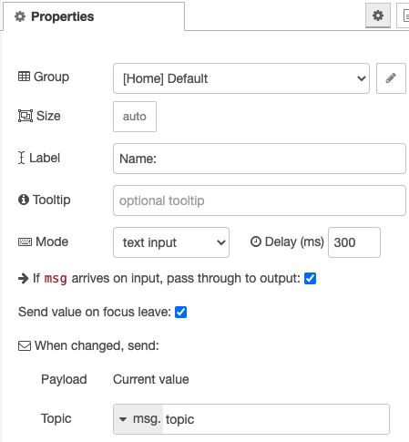
We will add a Switch, a Text Field, two Numeric Fields, plus a button to trigger the database INSERT.
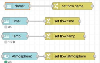
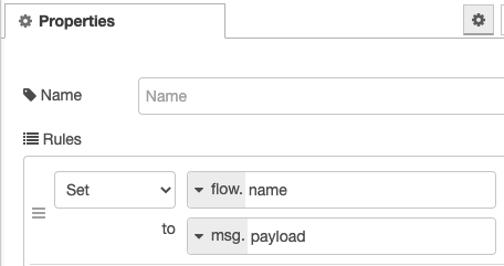
Each of the inputs (in light blue), will be configured with defaults, changing the Description to something useful to the user. The Change nodes in yellow will take the input and map it to the message. The settings for both are shown below with the inputs on the left and the change node on the right. You can extrapolate the other three configurations based on these examples.
Next, add a button along with a function node, another database connection (copy and paste the one from earlier) and a debugger message. Leave the button with default settings.

This function block will be more complicated, and will look like the following:
msg={
   name: "'"+flow.get("name")+"'",
   time: flow.get("time"),
   temp: flow.get("temp"),
   atmosphere:flow.get("atmosphere")
};

insert = "INSERT INTO recipes (name, time, temp, atmosphere) VALUES ("+msg.name+", "+msg.time+", "+msg.temp+", "+msg.atmosphere+")"
msg.topic = insert

return msg;
Here we are building up the message that will be passed along to the database connection. First we take the values from the input variables we assigned to the flow variables and set the values in the message to those values. Notice that we are wrapping the name value in single quotes as this will be passed to the database as a string.
Then, we set the insert variable equal to the INSERT query we are creating—we are simply building a string for the values to be inserted. Note that if you are using this in production, you will want to sanitize the data or use parameterized queries to prevent a SQL Injection attack. This is simply an example to get all of the pieces and concepts into place and does not include that additional effort.
Finally, we return the message after setting the topic and pass it along to the database connection node to INSERT the records.
The debug node uses the “complete msg object” in its configuration instead of the standard msg.payload as the complete msg object will show us all of the data involved in the message when it is sent to the debugger.
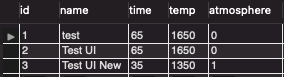
Once we enter values and press the button, we will see data populated in the database, as show below using MySQL Workbench.


Wrapping Up
This tutorial has us setup to integrate our groov View application with a database. We validated our Node-RED flows function to get data into and out of a database.
In the next post, we will set up data source tags in groov View to send and receive data into Node-RED, update our database interactions to use the groov View data instead of the Node-RED dashboard, and get data onto a screen.
In the last post we will show how this data integrates with the PLC logic so an operator can create a recipe, load it in the future and run it with the push of a button—all without having to manually update setpoints on all of the different variables.