How to Program Lead/Lag Pumping in Ignition
In most pumping applications—especially in water and wastewater—using a lead/lag/standby scheme for pumps is standard practice. It allows your system to operate at a low capacity, ramp up to meet increased demand, and spread the operational load across multiple pumps to reduce maintenance costs. In this post, we will describe how we approach these schemes from a control perspective and how we quickly integrate them with Ignition for operator control.
What is Lead / Lag / Standby, and Why Does it Matter?
Lead / Lag / Standby refers to how multiple pumps can be sequenced to operate as a single unit to meet variable pumping demand. If you have multiple pumps, you designate one to act as the lead, others to act as lag pumps, and some to be on standby. As pumping demand increases and the lead pump is at or near capacity for a specified period of time, you activate the lag pump(s). As the lag pumps approach near capacity, add standby pumps to meet the demand. When demand slows and the pumps are operating at minimum speeds, you turn them off accordingly in reverse order.
On a daily basis, you would typically alternate the lead pump to one that was in lag mode the previous day to spread the operational load around. With this strategy, you will have two pumps at similar maintenance levels rather than one pump absorbing 100% of the load.
For installations with more than two pumps, you can also designate one or more as the standby pump(s). These will not operate without manual starting/stopping, or they can be used in auto mode if desired. This approach allows you to easily take pumps offline for servicing, and further distribute the operational load.
How to Program Lead / Lag / Standby Controls
For our example, we will assume we have a four pump configuration with a lead, lag A, lag B, and a standby pump. Pumps will be designated as P-101, P-102, P-103, and P-104. Each day at midnight we will alternate the Lead / Lag A / Lag B / Standby sequentially, so P-101 will start out as lead and alternate as follows:
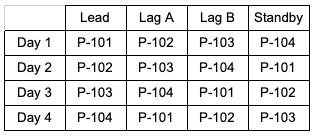
In this example, we will also assume these pumps are on VFDs so we can adjust speed, along with start and stop commands. We won’t worry about faults, alarms, or motor parameters here, this demonstration is more about how to simplify the Lead/Lag/Standby operation—not how to program a control system that is 100% ready for actual operation. We will assume the pumps are all the same hardware, and are pumping into the same pipe. Lastly, we will also assume everything is running in auto mode, and that we are controlling the level in a basin of influent to the plant.
Now, we will build a pump controller to handle the logic for our system and use the pumps as inputs and outputs to this system—along with our process variable so we can control everything appropriately. There are many ways to approach this, however we will go with the simplest strategy of using a single PID loop. We’ll think of our Lead, Lag A, and Lag B pumps as one cohesive unit, each providing ⅓ of our overall capacity. Then, we’’ll do our best to ensure and even flow into the plant. We will reduce the overall speed of the lead pump when we move into running the Lag A pump, and then reduce both pumps when we turn on Lag B. Finally, we will increase the speed when we turn off Lag B, and then Lag A.

For the inputs, we need the run status and speed of each pump along with the level in the basin. For this example, we will assume we have three pumps always available. For outputs, we will have a run command for the Lead/Lag A/Lag B pumps, and a speed command for each pump. We will also manage the pump configuration in the controller. The controller isn’t concerned with which physical pump is Lead/Lag A/Lag B, so we will simply use Pump 1, Pump 2, Pump 3, and Pump 4 for the pumps in our controller. This allows us to make the system as flexible as possible and use the same controller logic for many different groups of pumps.
First, we will build a Pump user defined type (UDT) in the PLC. This will hold all of the feedback and command tags for each pump. We will use this in our Add On Instruction (AOI) to simplify the tag management.
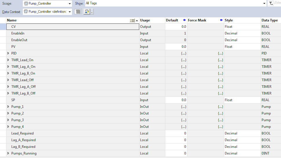
Next, we will add tags to our AOI for timers, the PID loop, and the pump tracking we will require for our operation:
Finally, we will build out the logic for the pump controller. First, we have a PID controller and are mapping the setpoint from our pump controller inputs to the PID controller.

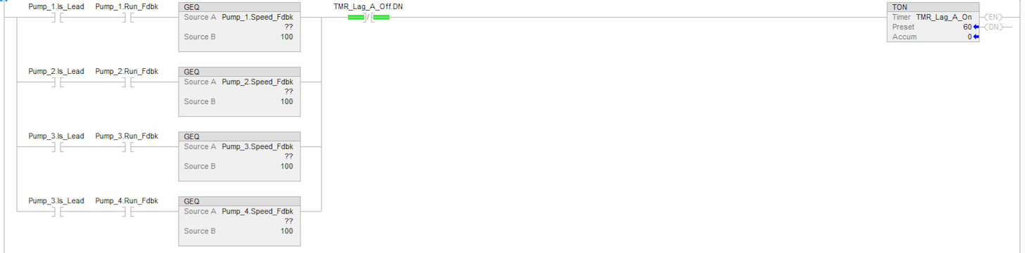
Next, we’ll set up all of our timers to manage starting/stopping the pumps. After the timers, we will manage each pump’s logic individually. We’ll start with checking to see if the lead pump is running. If it is running at 100% for one minute, we will signal the Lag A pump to start.
Similarly, if the Lag A pump has been running at 100% speed for 60 seconds, then we will start the Lag B pump.

To stop the pumps in the reverse order, we will use a similar approach to see if the pumps are running at or below 50% speed for 60 seconds. We’ll start with Lag B:

After we turn off the Lag B pump, we will want to shut down the Lag A pump in a similar manner. For the Lead pump, we’ll evaluate the output of the PID block to turn it off.

To start the lead pump, we will look at the output of the PID block, and if it is more than 5% we will turn the pump on. Similarly, we will turn on Lag A and Lag B if the timers have completed and they need to start to meet the demand:

Since from a PID perspective we are working with the pumps as a single unit of control, we will divide the total output by the number of pumps running, and apply that speed to each pump. In essence we will operate the output of the PID block from 0-300%, assigning 100% to each pump at maximum speed. This will help smooth the overall transition and keep a more consistent flow into the rest of the process when pumps start or stop.
To track this, we will simply count how many pumps are running:

Finally, we will start and stop the pumps as needed based on their Lead/Lag A/Lag B configurations:

Connect Your Lead / Lag / Standby Controls to SCADA
For connecting the signals from the PLC to our SCADA system, we will build out a User Defined Type (UDT) in Ignition to map to the PLC tags automatically based on the pump controller name AOI in the PLC. This allows us to create a tag in Ignition and have it automatically map everything, so we don’t need to spend a lot of time managing tags.
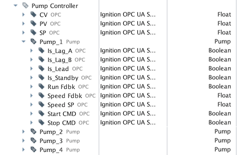
First we will set up a Pump UDT. This will match the tags in the Pump UDT in the PLC:

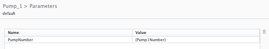
This UDT will have a PumpNumber Parameter we can use to map it to the tags in the PLC. For this project, the instances of these tags will have 101-104 as the parameter values to map to pumps 101-104 in the PLC:

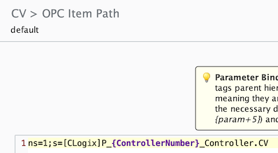
If you look at the OPC binding on a particular tag, you will see how we use the PumpNumber parameter in the OPC path to replace this value with the value of the parameter. This gives Ignition the path to the tag in the PLC, and makes everything work:

Now that we have our pump UDT, we need to also create a Pump Controller UDT. This will have our PV, SP, and CV, as well as four of the pump UDTs so we can see all of the data related to the pump controller in one spot:
Similar to the Pump UDT, we will include our Pump Controller number as a parameter, as well as the pump 1-4 values so we can map those to the instances of the Pump UDT within the Pump Controller UDT:
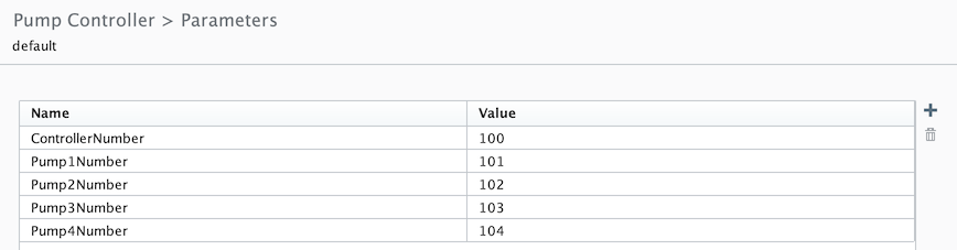
If you navigate to the Pump UDT within the Pump Controller UDT, you’ll see we are using the same curly bracket notation to take the value from the Pump Controller UDT and utilize it on the Pump UDT. This allows us to manage the parameters in a single location, and use them throughout the UDT.
If you look at the OPC item paths for the Pump Controller, you will see a similar format mapping the Pump Controller tags in the PLC
Programming the Lead / Lag / Standby Operator Interface
We will create templates in Ignition to program the interface. Then, we’ll put the template on a window, set the value of a custom property to match the tag name for our pump controller in Ignition, and automatically populate everything.
We will build a pump template to show the individual pumps, and a pump controller template to show the overall pumping operation based on our pump controller in the PLC.
Similar to the Pump and Pump Controller UDTs, we will first create a Pump Template to in the Pump Controller Template we will create afterwards.
We will be using Vision for this tutorial, but creating this in Perspective would follow a very similar process. First we will add a new template in the Templates section of the project browser called Pump. Then we will add the relevant items to the screen and name them for easy reference:


We will add two custom properties at the root level of the template. One for the Pump Controller tag path, and another for the specific pump number. This will allow us to reference a pump controller without having to change anything in our template, or on a specific pump within that controller.

As an example we will walk through the Fill color binding on the pump graphic. Other bindings (like labels) will have a very similar format. We will use an Expression binding since we’ll need an if statement along with the tag() expression function to get a tag value from a constructed path based on the controller tag path parameter.

If the pump is running, we want the fill color to be green, and if it isn’t running the color should be gray.

The pump is green when running
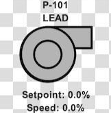
The pump is gray when it isn’t running
Now that we have a Pump Template, we can build out the Pump Controller template. We will drag four instances of the Pump Template to the new Pump Controller template, and set up our custom properties: one for the Pump Controller tag path, and one each for the pump number. We will also add two labels: one for the level, and one for the setpoint. We’ll also add a sparkline to display historical data for both.


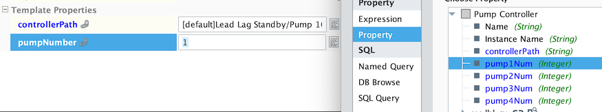
For the individual pump instances, we will bind the controllerPath custom property to the Pump Controller’s controllerPath custom property, and the pumpNumber property to the relevant pumpNum property from the Pump Controller template.
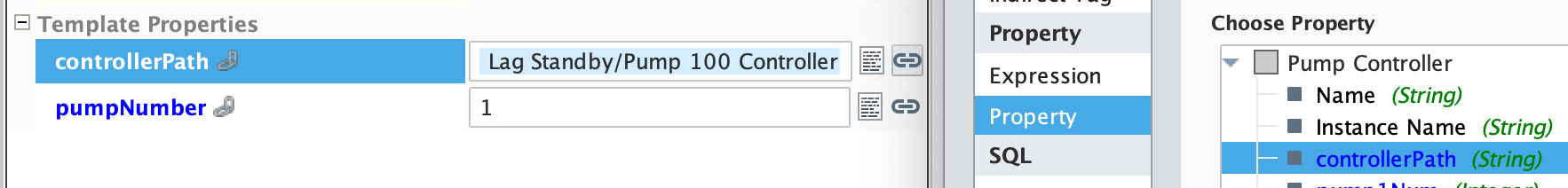
Our template is reay to go after we bind the labels and sparkline data to the tags based on the controllerPath property to the SP and CV tags.

Finally, we will drag this template onto a window, and set up the values of our pumpNum and controllerPath properties accordingly. Now we are ready to put this screen in front of the operators in a client.

Managing Maintenance
The last step of this process is to cycle through the pumps on a daily basis. For ease of discussion, we will assume the pumps will cycle at midnight. This is a relatively simple piece of logic to write.
When the PLC clock is at midnight (assuming Pump 1 is lead, Pump 2 is Lag A, Pump 3 is Lag B, and Pump 4 is standby) we will make Pump 2 the lead, Pump 3 Lag A, Pump 4 Lag B, and Pump 1 Standby. Then we will continue cycling on subsequent days. If a pump is out of commission for some reason, it will either require additional logic so that we can mark it out of service, or the operators will need to manually configure the pumps—otherwise the out of service pump could be designated as a pump that needs to run.
We will track a four day cycle since we have four pumps, and set up the logic to cycle accordingly. There are numerous ways we could implement this logic, and there are pros and cons to each, this method was simply quick for our example tutorial:

Here, we are getting the system time and a current day tag separately in the logic, and simply using a counter to track the overall cycle to set the pump configurations. Additionally we could ensure pumps are turned off when cycling if we wanted, and could get into more complex schemes if we desired, however this is meant to serve as a baseline example, not an advanced control system ready for large scale production.
Closing
To summarize, we set up tags and logic in our PLC to manage Lead/Lag/Standby pump operation using a pump controller instruction we wrote. We mapped these tags to our SCADA system, in this case Ignition, using a User Defined Type (UDT). We created templates to display everything based on the UDT, and put the template on a window.
This tutorial nshould give you a great starting point for implementing a similar setup at your facility, and if you would like to get more in depth design help, please contact us!