Using Node-RED on an Opto22 groov RIO

After reviewing our groov RIO series part 1 and part 2, you likely have data coming into your RIO. Now, let’s start using that data. While you could easily use Codesys to implement control logic with the RIO as part of a larger system, today we’re going to use Node-RED on the RIO for basic data manipulation, control, and integration.
Node-RED is a graphics-based programming environment for quickly building complex systems using a myriad of different tools—with a lot of the heavy lifting already done for you. If you have worked with home automation or used a Raspberry Pi in the past, you have probably seen or used Node-RED before.
Enable Node Red on the groov RIO
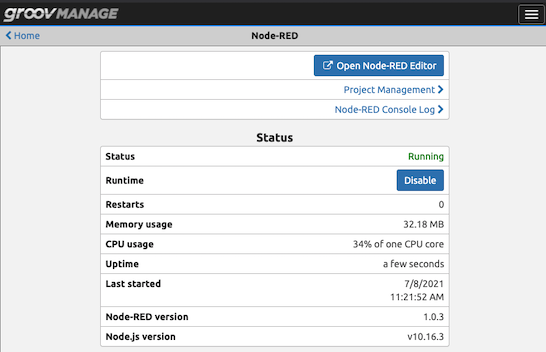
The first step when using Node-RED on your groov RIO is to enable it. Go to the groov Manage homepage, then click the “Node-RED” button. This will bring you to the Node-RED configuration page. Here you will need to click the “Enable” button and you are ready.

Once Node-RED is enabled, click the “Open Node-RED editor” button to open the Node-RED editor where you can build your Node-RED flows.

Install groov I/O Nodes
Now that you have accessed Node-RED on the RIO, we can install the groov nodes for the I/O channels on the groov RIO—as well as the memory map for non-I/O channel data reads/writes.

To add the groov nodes, click on the hamburger (toggle) menu in the upper right of the Node-RED page, then select “Manage Palette”.

This will bring up the palette management menu. Select the install tab, then search for “groov-io” without quotes. Once it shows up in the list, click the install button next to it on the right to install it on your Node-RED instance.
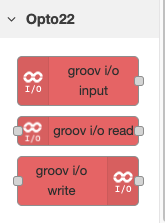
Once you have installed the groov-io nodes in your palette, you will see them by scrolling to the bottom and looking on the left side. Now you can configure them to get data in and out of your groov RIO.
Configure the groov I/O Nodes
Now that you have the groov I/O nodes installed, you can read data from an input, write to an input, or read data from the groov RIO as part of your flows. The groov I/O input will run once when the flow starts, so we will focus on using the groov I/O read node in the middle. It will let us trigger reads of RIO data—including from the mapped memory space which we will use for PID control in our post about PID control with the groovRIO.
Drag and drop this node to your flow, along with the debug node and the inject node—both of which are the first two nodes listed under “Common” on the left side of the Node-RED page.
The inject node will allow us to cyclically trigger a read of RIO data, and the debug node will let us write it to the debug console in Node-RED which will display the values ready by the node to verify everything is working correctly.
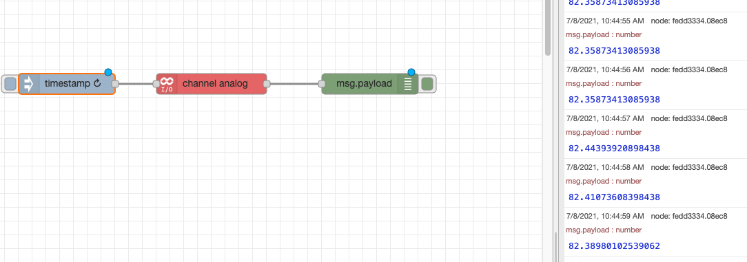
Put the inject node on the left, the groov I/O read in the middle, and the debug on the right. Then, click the circle on the debug to drag a line to the left side of the read node, then the left side of the read node to the debug node.

Setup the Inject Node
For this post, set up the inject node as a timestamp with a cyclic repeat of one second. This will trigger the node every second. The line connected to the groov I/O read node will cause it to execute once every second, and the line from that to the debug node means it will log the value to the debug console every time it executes.
To configure the inject node, double click on it to open the configuration window. The node will default to timestamp, just change the “Repeat” to “Interval” and enter 1 second.

Configure the groov I/O Node
Double click on the groov I/O node. Next, you will need to add the groov RIO, by clicking the pencil next to “Add new groov-io device.” Since we are using Node-RED on the RIO itself, you can enter “localhost” with no quotes, for the address.

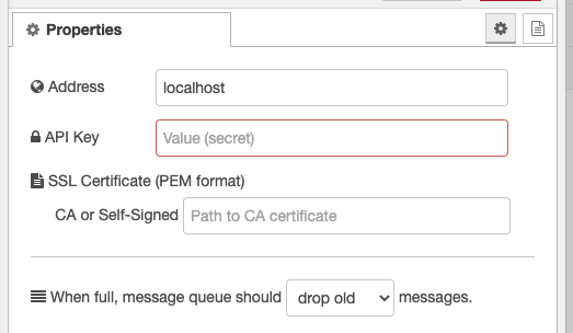
Next you will need the API key from your RIO. To get this go to the groov Management homepage-Accounts-Users. Then, select your user account. On this page you will see the API key listed. Copy it and paste into the API key section of the node configuration page.


Finally, click '“Save/Update” to save the changes to the RIO device, then select “Analog Channel” then Channel 0 in the main node configuration screen. Next, click “Deploy” on the flow to save the flow to the server and start it. You should then see data populating on the right side of the screen which will correspond to the value coming in from the RIO.
Congratulations! You have unlocked the power of Node-RED on your groov RIO! Now you can dig deep into the possibilities of using Node-RED as the brains of your control strategy, and you can get data out of your RIO.
Read the next post in this series to open the door to PID control using the built-in PID controllers in the RIO, and will show you how to write data back to the RIO from Ignition.
Thanks for reading to the end! If you have a groov RIO, any other Opto22 products, or have any questions on anything you have seen here please drop us a line!